Getting good RF performance isn’t just about choosing the right schematic or laminate. Layout decisions made during PCB design directly affect how easy it is to validate the board once it’s fabricated.
I wanted to start a discussion on the design practices that make RF boards easier to measure, troubleshoot, and optimize during validation.
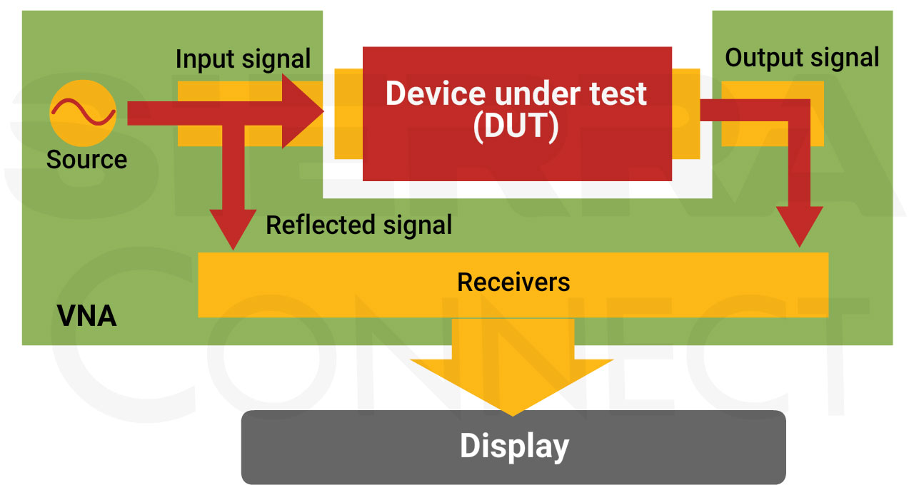
Successful RF validation starts long before connecting a vector network analyzer (VNA). PCB stack-up, controlled impedance, connector launches, grounding, and transmission-line geometry all influence the accuracy of RF measurements.
Poor layout can make it difficult to determine whether unexpected results come from the design itself or from the measurement setup.
Validation becomes much easier when measurement is considered during the design stage.
Some practical recommendations include:
Add dedicated RF test structures or calibration coupons where appropriate
Leave enough space around RF connectors for VNA calibration and probing
Document the target impedance and operating frequency range in your fabrication notes
Review the stack-up with your fabricator to ensure dielectric thickness and material properties match the design assumptions
Comparing measured S-parameters with simulation results is one of the most effective ways to identify impedance discontinuities, excessive insertion loss, and unexpected resonances before a design moves into production.
For a deeper look at RF PCB design, VNA setup, S-parameter interpretation, Smith Charts, and practical validation techniques, check out this webinar: RF Design and Validation with VNA Demonstrations.