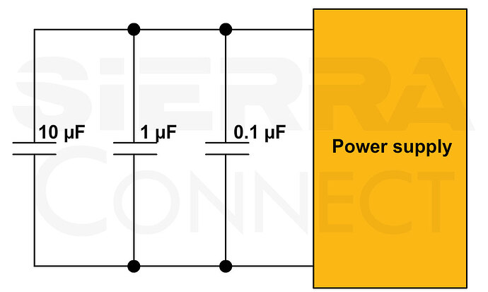
A decoupling capacitor (decap) is a passive electronic component placed between a power supply and an IC on a PCB. Its primary function is to filter out voltage spikes and high-frequency noise, providing a stable DC supply to sensitive components.
Decaps serve as local energy reservoirs for sensitive parts such as ICs. They quickly supply current during sudden switching events and prevent voltage drops and noise through the power rails. The capacitor values typically range from 0.01 µF to 100 µF, depending on the type and frequency of noise they need to filter.
Best practices to choose decoupling capacitors:
-
Select a capacitor with a voltage rating that is at least 1.5 times higher than your power supply voltage (e.g., 6.3V or 10V for a 3.3V system).
-
Each IC should have at least one dedicated decap. High-speed or high-pin-count devices may require multiple capacitors.
-
Choose low-ESR ceramic capacitors with stable dielectrics (e.g., X7R) for high-frequency performance. Avoid high-ESR electrolytic capacitors for high-speed designs.
Layout tips for placing decoupling capacitors in your PCB:
-
Place capacitors close to the IC’s power pins to minimize loop inductance. Use short and wide traces to connect to power and ground planes.
-
Connect the capacitor’s ground pin directly to a low-impedance ground plane to minimize noise coupling.
-
Use multiple decaps of the same value near the power supply. If not possible, place the lowest-value capacitor closest to the supply, as shown in the image below.

