Choosing the right PCB material is one of the most critical decisions in RF and microwave designs. These circuits have differences in operating frequency, electrical behavior, and loss mechanisms.
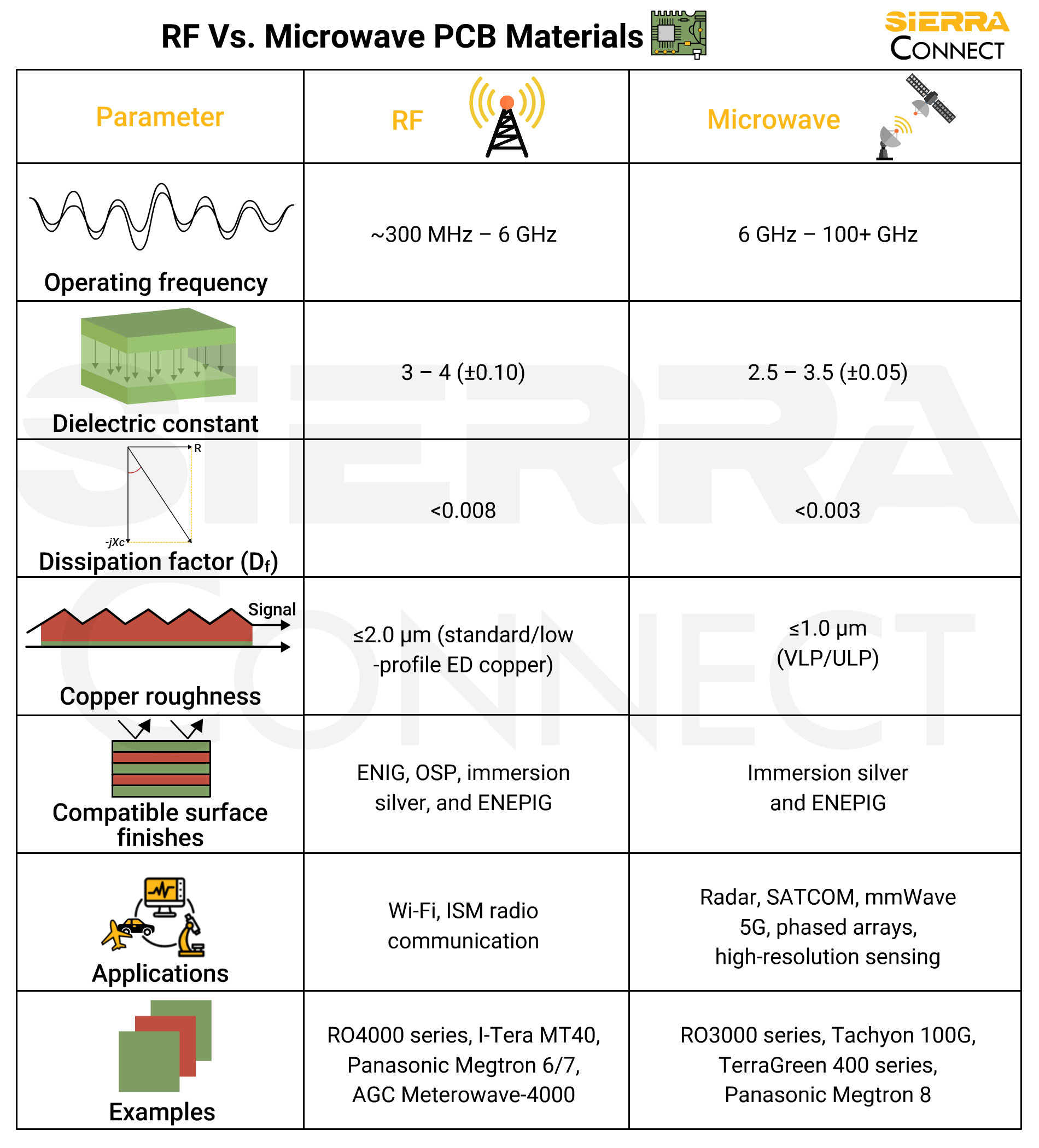
The infographic above compares the key parameters.
Operating frequency
RF circuits typically operate from a few hundred megahertz up to around 6 GHz. In this range, standard laminate properties, copper profiles, and fabrication tolerances generally provide predictable impedance control and acceptable signal loss.
Microwave circuits operate above approximately 6 GHz and extend into millimeter-wave frequencies beyond 100 GHz. At these frequencies, wavelengths become very short, and PCB features such as trace width, dielectric thickness, copper roughness, and surface finish strongly influence electrical behavior. Even small material variations can lead to measurable phase error, impedance mismatch, or insertion loss.
This is why microwave designs demand tighter control over material properties compared to RF designs.
Dielectric constant (Dk) and tolerance
The dielectric constant determines how fast signals propagate through the board and directly affects impedance control. RF PCB materials commonly have Dk values between 3 and 4, with typical tolerances around ±0.10. This level of variation is usually acceptable for RF designs such as Wi-Fi, ISM radios, and low-GHz communication systems.
Microwave materials use lower and more tightly controlled dielectric constants, typically between 2.5 and 3.5, with tolerances around ±0.05. At high frequencies, even small Dk variations translate into phase mismatch, frequency shifts, and amplitude variations. For microwave designs, Dk stability is often more important.
Dissipation factor (Df)
The dissipation factor (Df), also called loss tangent (tan δ), is directly related to how much signal energy is converted to heat in the dielectric material. Materials with higher Df cause more signal loss (attenuation) due to heat. RF materials typically have dissipation factors below 0.008, which is sufficient for short-to-moderate trace lengths and low-GHz applications.
In microwave circuits, dielectric loss becomes far more significant due to higher frequencies and longer effective trace lengths. As a result, microwave materials target Df values below 0.003. At microwave frequencies, dielectric loss combines with conductor loss, making low-Df materials essential for maintaining acceptable insertion loss and signal-to-noise ratio.
Copper roughness
Copper surface roughness is a critical differentiator between RF and microwave PCB materials. At low frequencies, current flows through the entire copper cross-section. As frequency increases, current concentrates near the copper surface due to the skin effect.
RF laminates typically use standard or low-profile electrodeposited (ED) copper with roughness values up to about 2.0 µm. At radio frequencies, the signal attenuation caused by this roughness is generally low.
Microwave materials require much smoother copper surfaces, typically ≤1.0 µm (very-low-profile (VLP) or ultra-low-profile (ULP) copper). Rough copper increases conductor loss, phase distortion, and impedance variation at high frequencies. Smooth copper significantly improves insertion loss in microwave designs.
Compatible surface finishes
Surface finish selection affects solderability, reliability, and high-frequency performance. RF designs are compatible with a wide range of finishes, including ENIG, OSP, immersion silver, and ENEPIG.
Microwave designs are more sensitive to surface finishes. Immersion silver is commonly preferred due to its low insertion loss and excellent high-frequency performance. ENEPIG is also used, particularly in high-reliability applications, but nickel thickness must be tightly controlled to avoid excess loss.
Applications
RF materials are widely used in consumer and industrial electronics, including Wi-Fi modules, ISM radio systems, wireless sensors, and communication devices operating at low-to-mid GHz frequencies. These applications balance performance with cost and manufacturability.
Microwave materials serve applications where precision and performance are critical, such as radar systems, satellite communication, millimeter-wave 5G infrastructure, phased-array antennas, and high-resolution sensing systems. In these applications, material stability and loss performance are often more important than cost.
Material examples
Typical RF materials include Rogers RO4000 Series, Isola I-Tera MT40, Isola Astra MT-77, Panasonic Megtron 6/7, and AGC Meterowave-4000. These laminates provide good electrical performance with manageable fabrication requirements and are compatible with standard PCB processes.
Microwave materials include Rogers 3000 Series, Isola Tachyon 100G, Isola TerraGreen 400 series, and Panasonic Megtron 8. These materials offer ultra-low loss, stable dielectric properties, and excellent high-frequency performance, but require tighter fabrication controls and higher manufacturing costs.
The distinction between RF and microwave PCB materials is not defined solely by frequency. It is driven by loss sensitivity, material stability, copper surface effects, and fabrication tolerance. RF materials prioritize cost-effective performance for low-to-mid GHz applications, whereas microwave materials are engineered for precision, consistency, and minimal loss at extreme frequencies.
Understanding these differences allows you to make informed decisions, selecting materials that meet electrical requirements without unnecessary cost or manufacturing complexity.